
Our capabilities
Our clients hire us at various stages of the project life cycle for specific tasks or we become part of the integrated team of clients providing ongoing technical advice and project management services.
The project examples provided here are just a sample of our capabilities. We look forward to exploring how we can positively impact the direction of any project throughout its entire life cycle.
Our experience in large projects includes, but is not limited to:
- Design of devices and mechanisms through Finite and Discrete Element Analysis.
- Pulp, fluid and gas behavior simulations
- Design, manufacture and assembly of multidisciplinary engineering teams
- Planning and control of complex projects with multivariable control
- Development and stimulation of innovations
- Design, manufacture and service of gas and fluid treatment equipment
- Design and manufacture of robotic devices
- Automatic control of industrial plants
- Analysis and planning of maintenance actions for industrial plants

Our projects
MCC – CONTINUOUS CONDITION MONITORING IN CONVEYOR BELTS
Distributed Detection
The MCC is a monitoring system is based on a distributed fiber optic sensor, which by means of dispersion detection technology, allows the diagnosis of the idlers in a predictive way.
| DATA SHEET Continuous Condition Monitoring by Distributed Vibration Sensor |
Oxer’s Continuous Condition Monitoring (MCC) system is a set of Hardware and Software based on a distributed vibration sensor aimed at monitoring conveyor belt idlers. This technology allows to have 1 monitoring channel for every 8 centimeters of fiber optic cable installed on its conveyor belt, with a guaranteed spatial resolution of 40 centimeters, which allows complete control of vibrations in the idlers, which corresponds to a crucial factor in the preventive analysis of bearing failures.
State-of-the-art Technology
We based this technology on optical reflectometry technology, therefore, with the installation of a single cable along the transport structure, a measurement channel is generated every approximately 8 centimeters (acquisition limit) in a multiplexed manner in a single measurement, with a guaranteed total spatial resolution of 40 centimeters.
Characteristics
- Distributed vibration detection system.
- Based on OTDR.
- 40 cm spatial resolution.
- Possibility of simultaneous multichannel monitoring.
- Continuous monitoring with alarm system.
- Event database storage.
- Analysis in standard single mode telecommunications fibers.
- Possibility of adjustment to a custom measurement length.
Very anticipatory control
The system is in charge of analysing the frequency of the vibrations that occurred telemetrically in the idlers of the transport structure, generating reports through the analysis of patterns, and alerts through a personalized graphical interface. It monitors the evolution of faults, detecting variations in the behavior of vibration frequencies long before there is a fault behavior.
Large measuring range
The ranges vary according to the amount of fiber installed, and depend exclusively on the physics of the electromagnetic wave involved (Light), through the equation of the pulsed sampling period.
Robust installation
We use 4-wire fiber optic redundant cables, reinforced with metal and high-density polyethylene to ensure fiber optic viability in extreme terrain. The installation corresponds to a non-invasive process and is carried out using self-fixed clips. This system will allow the installation of the service during the scheduled shutdown processes, or when the customer deems appropriate without altering the maintenance processes.
HMI User Interface
The system provides an intuitive and self-explained user interface, with its own and personalized programming for each belt, integrated into the equipment, which allows the operator to monitor in real time the status of the belt sections, as well as the existing trends of operating frequencies in the posts. In addition, there is a record of current, previous and notified alerts to operators.
The interface is customizable for each conveyor belt. A preliminary study of the terrain and exact position of each polines station is carried out, with constant software updates according to the progress in the generation of patterns (the system evolves as the monitoring time is longer).
Technical specifications
| Performance | ||
| 1 per strap on both sides of the strap | Number of cables installed | |
| Fiber optic cable type | Redundant 4 fibers, Reinforced metal and high density polyethylene. | |
| Sensor configuration | Phase Sensitive OTDR | |
| Bandwidth | 200 kHz | |
| Measurement parameters | Frequency in each position, generation of reports of identified events | |
| Maximum fiber length per span | 413 meters for a 200 kHz band (see graph of physical limitations) | |
| Spatial resolution | 40 centimeters | |
| Spatial precision | +/- 20 centimeters | |
| Sampling interval | ~ 12 channels per meter | |
| Acquisition time | 1 second per scan + 5 seconds of analysis | |
| Number of scans per sample | 10 | |
| General | ||
| Graphic interface | Integrated PC with analyzer | |
| Communication | Field HMI, remote communication by TeamViewer or related software (Windows) | |
| Required connection | Wifi Internet or similar | |
| Output formats | Visual alerts, trend lines (frequency), Position and label. | |
| Data storage | Internal, report generation | |
| Data format | .csv, .txt, .xls Automatic generation of reports in .pdf | |
| Optical connections | FC / APC | |
| Wavelength | 1550 nm | |
| Operating temperature | -15 ° C / 60 ° C | |
| Power supply | 220 V power cable | |
| Characteristics | ||
| Measurement mode | Automatic | |
| Analysis of data | Localized frequency spectrum | |
| Alarms and warnings | Automatic generation of alarms, periodic reports | |
| Maintenance | Constant updating according to the study of the patterns generated in its installation, initially with preventive maintenance, and later predictive (estimation of the next failure) | |
| Mechanical resistance of fiber optic cable | Tensile strength: 1500 N Crushing strength: 2000 N Impact resistance: 25 N | |
Technology
- The system is based on optical reflectometry in the time domain, presenting sensitivity to light phase changes due to pressure variations along the optical fiber (∅ – OTDR). When the frequency of pressure variations is analyzed, it is characterized as a vibration in the frequency domain.
- The vibrations affect the transmission of light through the optical fiber, affecting the magnitude of the losses associated with the photons reflected up to the beginning of the fiber. These reflections are acquired by synchronizing a pulsed wave train with a sophisticated acquisition system, where each pulse characterizes the current condition of the fiber, translated into the measurement of the magnitude in a distributed manner in an instant of time. This instantaneous characterization is known as a trace, where each trace corresponds to a sample.
- The system is responsible for processing a large volume of samples, completing an acquisition. Each acquisition is translated into an updated diagnosis of the status of faults and alarms.
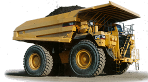
OVERSIZE DETECTOR ON CAEX TRUCKS
The oversize detector is a device that is installed in the hopper of extraction trucks to detect the presence of abnormally oversized ore. The system works on the basis of a spectral analysis of the vibration frequencies.
The system works based on the analysis of the integrated signals generated by various accelerometers installed in the corners of the hopper. The vibration generated by a normal loading operation of the truck in front of the shovel, in addition to the behavior of the vibration spectra during the journey of the truck to the crusher, defines a vibration pattern in the time domain that can determine the granulometric content of mineral. in the hopper. There is a significant difference in density between a solid material and the same ground material. This difference can be up to 50% and generates different vibration spectra. With the integrated information from the accelerometers, a three-dimensional image of the hopper content is constructed and density concentrations can be differentiated, allowing the identification of a solid body with proportions abnormally higher than the crusher’s process capacity.
The system incorporates an artificial intelligence mechanism that learns over time to optimize diagnosis and resolution. The type of technology used in this project is a mixture of Spectral Analysis of vibrations together with artificial intelligence.
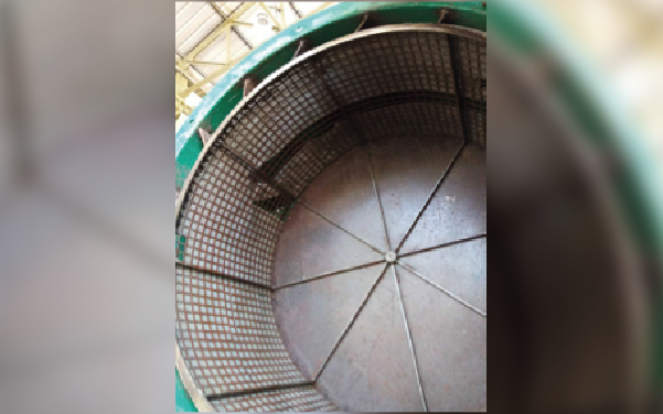
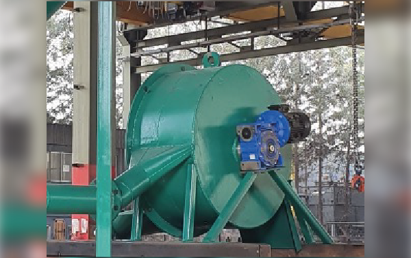
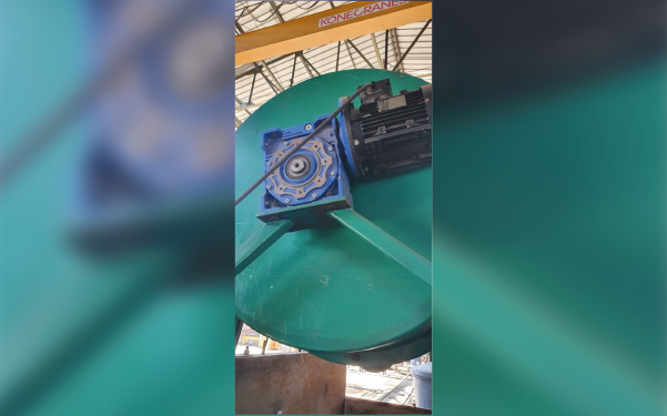
SOLIDS SEPARATOR
Filtering in the industry
In many fields of industry, it is necessary to filter or concentrate a mixture by means of filtration. Filtration is the process of separating solid particles from a liquid using a porous material called a filter. This technique consists of pouring the solid-liquid mixture to be treated through a filter that allows the passage of the liquid but retains the solid particles. This filtration process has a limit that is reached when the solid particles have saturated the filter openings.

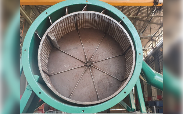
How it works
In the Solids Separator, the flow of material to be filtered enters an intake chamber where it advances in contact with a cylindrical filter drum that rotates at approximately the same speed as the flow. The liquid is able to pass through the filter component to the product chamber and from there immediately to the outlet duct, but the solid particles are retained on the outer surface of the filter element. At the end of the drum turn, the filter element is saturated with solid particles, at which point a small flow of high pressure clean water pushes the solid particles upstream, cleaning the surface of the drum in preparation for the next turn.
The solid particles, now mixed with a smaller amount of water, leave the filter chamber to the concentrate pipe. Energy is required only to move the filter drum in the same direction as the flow, and to compress a small fraction of the water at high pressure and drive it through the injectors. Oversize reject material is ejected through the lateral outlet on the perimeter of the drum at 270 degrees opposite the inlet flow.
Industrial applications
There are endless applications for this device because there are so many instances in industry where filtering is required. The virtue of this equipment is that it does not require stopping to change or clean the filter element. The other variable is cost, because by being such a simple piece of equipment, it has a low investment cost and low operating cost.